Understanding Gear Reduction and Motor Efficiency
Learn how gear reduction multiplies torque, affects speed, and influences motor efficiency, with tips to size ratios, curb losses, and boost performance.
Foundations of Gear Reduction
Gear reduction transforms a motor's high-speed, low-torque output into lower speed with higher torque, creating valuable mechanical advantage for tasks in the motors category. The gear ratio—often expressed as driven teeth to driver teeth—sets how much the output speed drops and how much torque rises. In an ideal world, power remains constant across the gearbox, but real systems experience losses, so output power is slightly lower. A higher ratio multiplies torque while reducing speed proportionally, allowing small electric motors to drive heavier loads without stalling. Designers often stack stages to achieve larger reductions, trading added complexity for compact force delivery. Good gearing also smooths motion, mitigates cogging in some motor types, and positions the motor in a healthier operating band. However, it introduces backlash, adds inertia, and may elevate noise if the gear type is not well chosen. Understanding these fundamentals helps set a clear path from required load behavior to an efficient, durable, and predictable drive system.
How Motor Efficiency Works
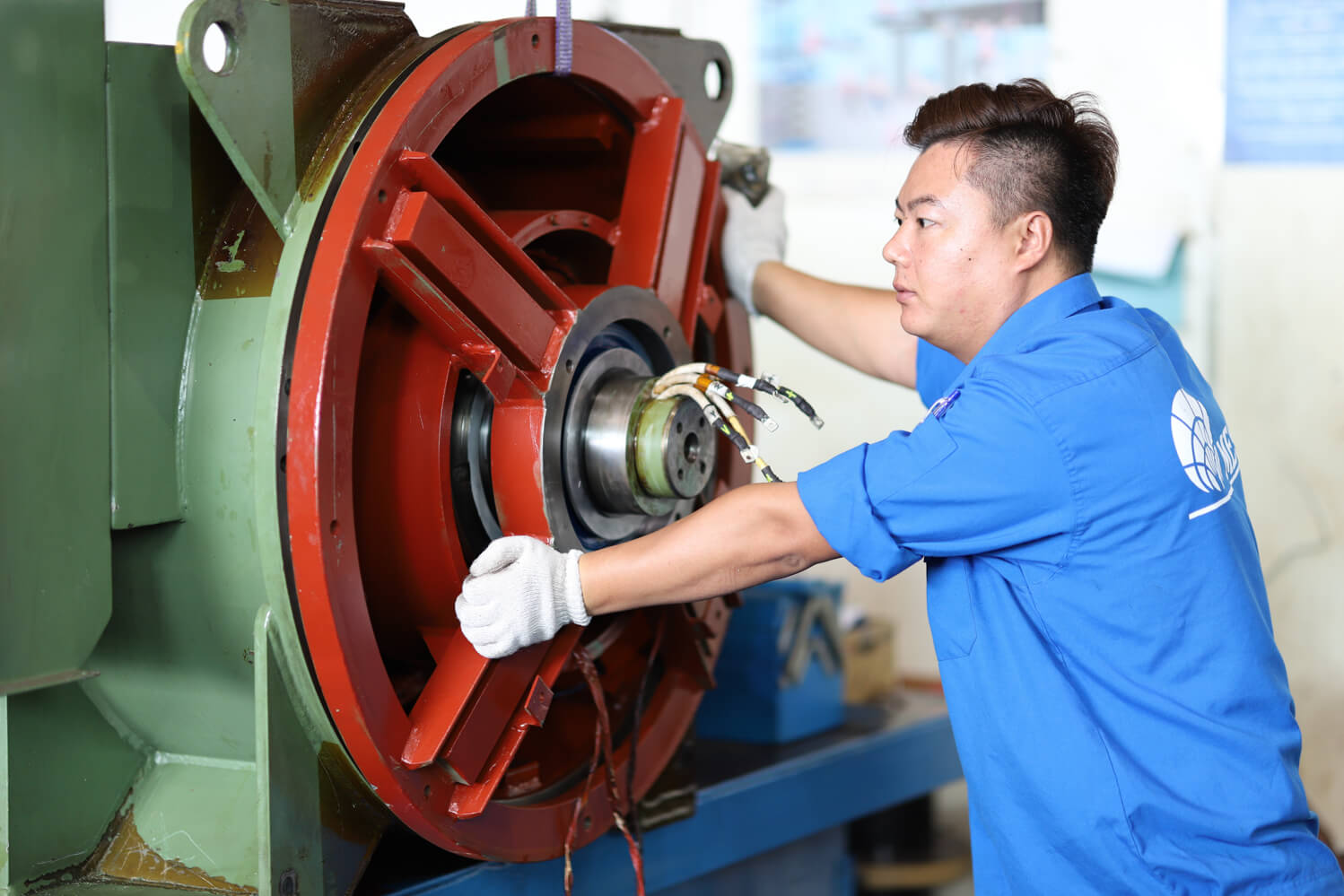
Motor efficiency is the ratio of mechanical output power to electrical input power, and it shapes energy use, heat generation, and runtime reliability. Losses occur in multiple places: copper losses scale with current, core losses arise from magnetic cycling, and mechanical losses include friction and windage. Drive electronics contribute additional losses in switching devices and wiring. Most motors have an efficiency curve that peaks at a moderate load and speed; too light a load wastes energy overcoming fixed losses, while too heavy a load drives up resistive heating. Efficiency also depends on control strategy: techniques like vector control, proper commutation, and optimized PWM can reduce current ripple and iron loss. Supply voltage and commanded speed affect where the motor lands on its torque–speed curve, which in turn influences temperature rise. Choosing a motor and gearbox combination that keeps operating points near peak efficiency yields cooler operation, longer life, and lower energy costs without sacrificing performance.
Matching Gear Ratios to Loads
Selecting the right gear ratio begins with the load. Determine required output torque from application physics—force and radius for rotary tasks, or linear force for leadscrew systems—and add estimated friction, gradients, and safety margin. Next, place the motor within a speed range where it runs efficiently and where its torque curve provides healthy headroom over the demand. Ratio choice also controls reflected inertia: the load's inertia divided by the square of the gear ratio appears at the motor shaft. A higher reduction lowers reflected inertia, easing acceleration and trimming current spikes during starts and reversals. Consider duty cycle, peak versus continuous torque, and shock loading to avoid thermal or mechanical overloads. Pay attention to backlash and stiffness for positioning tasks, and to backdrivability and holding torque for vertical or safety-critical axes. When in doubt, iterate: evaluate a candidate ratio, simulate acceleration and stop times, estimate current and temperature rise, and refine until dynamics, efficiency, and lifetime targets harmonize.
Trade-Offs: Speed, Torque, and Heat
Gear reduction is a balancing act among speed, torque, and heat. For a given external load, more reduction typically lowers motor current, cutting I²R losses and keeping winding temperatures in check. Yet additional stages introduce mechanical losses, so there is a sweet spot where total system efficiency is highest. If the ratio is too low, the motor works hard at low speed, risking overheating and sluggish response. If the ratio is too high, you sacrifice top speed, increase gearbox losses, and may add compliance or noise. Consider the application's cycle time: frequent starts demand margin for surge current and thermal transients, while steady operation rewards a ratio that places the motor near its peak efficiency. Also factor in acoustic limits, vibration, and lubrication regimes; overdriving a gearbox at excessive input speed can shear lubricant films and shorten life. The optimal design respects motor thermal limits, gearbox rating, and the true motion profile, not just the headline load number.
Gearbox Types and Their Impact
Different gearbox architectures shape efficiency, stiffness, and packaging. Spur gears are simple and efficient, offering predictable behavior and easy maintenance, though they can be noisier. Helical gears run smoother and quieter with higher load capacity, at the expense of axial forces and slightly greater friction. Planetary gearboxes deliver high torque density and compact layouts with good stiffness, making them popular in robotics and industrial drives. Worm gears provide large reductions and can be non-backdrivable, useful for holding loads, though they typically suffer lower efficiency and more heat under sustained duty. Cycloidal and strain-wave styles excel in precision and shock resilience, trading some efficiency and requiring careful lubrication. Each type exhibits characteristic backlash, stiffness, and noise profiles that interact with the motor's control loop and the application's precision needs. Choosing wisely means aligning torque, ratio, duty cycle, and acoustic targets with the gearbox's mechanical strengths and recognizing how these traits influence overall motor efficiency.
Calculating and Measuring Performance
A sound workflow blends calculation with measurement. Start by estimating load torque from geometry and forces, then add friction and safety factors. Select a gear ratio that keeps required motor torque below continuous limits while placing nominal speed in an efficient region. Check reflected inertia and verify acceleration, deceleration, and stopping distances match the motion profile. Next, validate on hardware: measure voltage, current, and speed to compute input power and mechanical output. Track temperature rise on windings and gearbox to confirm thermal margins under worst-case duty. Observe noise and vibration, which hint at misalignment or improper tooth contact. Use a torque sensor or dynamometer when possible to quantify system efficiency and gearbox losses. If measurements diverge from predictions, refine friction estimates, revisit alignment, confirm lubrication, and adjust control parameters. Iterating through this loop tightens models, reveals real-world constraints, and converges on a drive solution that balances performance, reliability, and energy economy.
Best Practices for Longevity and Reliability
Long-lived, efficient motor-drive systems follow disciplined practices. Ensure precise alignment, rigid mounting, and proper lubrication to minimize friction and tooth wear. Choose a controller strategy—current limiting, soft start/stop, and appropriate braking—that avoids unnecessary heating and mechanical shock. Size cables and power supplies to curb voltage sag, and keep ventilation clear to manage temperature. Select gear materials and seals for the environment—consider dust, moisture, and washdown—so contamination does not erode efficiency. For positioning tasks, minimize backlash with preloaded or low-clearance designs, and tune control loops with the gearbox's stiffness in mind. Establish maintenance intervals for lubricant changes and fastener inspection, watching for vibration shifts that indicate early wear. Avoid chronic operation at the extremes of torque or speed, where losses and stress peak. By pairing thoughtful gear ratio selection with careful integration, monitoring, and upkeep, you preserve motor efficiency, protect components, and keep motion smooth, predictable, and cost-effective over the system's life.