Motor Cooling Methods Explained: Air, Liquid, and Heat Sinks
Learn how motors shed heat: air vs. liquid cooling and heat sinks explained, with pros, cons, selection tips, and maintenance for peak reliability.
Cooling Overview. Motors transform electrical power into motion, and in the process they generate heat from copper losses, core losses, and friction. Effective cooling keeps windings, magnets, and bearings within safe limits, preserving efficiency, torque capability, and insulation life. The three foundational strategies are air cooling, liquid cooling, and heat sinks, all guided by the physics of conduction, convection, and radiation. A reliable design builds a clear thermal path from the stator and rotor to the environment while minimizing thermal resistance and avoiding hot spots. Factors like ambient temperature, altitude, duty cycle, and enclosure rating shape the best approach. In compact, high-power-density motors, even small thermal improvements can unlock substantial performance, whereas robust industrial machines may favor simplicity and maintainability. Understanding where heat is made, where it gets trapped, and how it escapes enables smarter choices about materials, geometry, fans, fluids, and monitoring, ensuring the motor delivers consistent output without premature wear or derating.
Natural Air Cooling. Many motors rely on passive, air-based convection where heat flows from the windings to the frame and then to the air. Designs with finned housings increase surface area to promote heat dissipation, while enclosures such as TEFC and open-frame styles trade off protection, airflow, and dust tolerance. Success depends on clear airflow pathways, proper mounting orientation, and steady ambient conditions; even small obstructions can raise temperature rise. Surface finish, paint thickness, and fin spacing matter because they influence boundary layers and radiative exchange. Natural convection excels for moderate loads, intermittent duty, and environments that reward simplicity and low maintenance. However, it can struggle with high power density, elevated ambient temperatures, or installations with restricted airflow. Designers often add shrouds or baffles to steer air across hot sections and avoid recirculation. Regular cleaning helps maintain performance, as accumulated dirt or oil films reduce effective surface area and increase the overall thermal resistance.
Forced Air Cooling. When passive methods are not enough, fan-assisted air cooling introduces axial or centrifugal blowers to move more air over hot surfaces. Integrated shaft-driven fans are common on industrial motors, while compact systems may use external blowers or ducted airflow for targeted cooling of end turns, housings, or drive electronics. The key is matching fan curves to system backpressure, ensuring the desired flow rate at operating conditions. Proper duct design, smooth transitions, and avoidance of sharp bends reduce losses and help distribute airflow uniformly, preventing hot spots. Variable-speed control via simple voltage adjustment or PWM lets airflow scale with load to balance noise, efficiency, and temperature rise. Filters can protect internal components but add resistance and require maintenance. Bearings, fan blades, and mounts should be specified for vibration, expected contamination, and run time. With thoughtful implementation, forced air significantly boosts capacity without the complexity of liquid loops, yet it still remains serviceable and cost-effective.
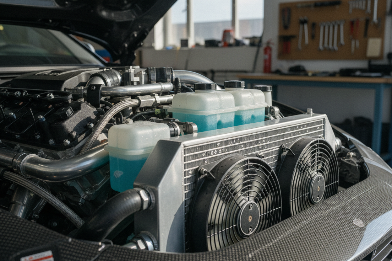
Liquid Cooling. For the highest power density, liquid cooling provides superior heat capacity and heat transfer compared with air. Solutions include cooling jackets integrated into the motor housing, cold plates, or embedded channels carrying water-glycol or specialized dielectric fluids. Design revolves around achieving good conduction from windings and core to the liquid pathway, then rejecting heat through a radiator or heat exchanger. Critical parameters include flow rate, pressure drop, pump selection, and expansion control, all tuned to maintain stable temperatures under peak loads. Material compatibility and corrosion management are essential; inhibitors and proper fittings reduce risk of leaks or galvanic issues. Quick-disconnects, leak detection, and thoughtful routing improve serviceability. Liquid cooling shines in traction drives, high-speed spindles, and compact servo systems where airflow is limited or noise-sensitive. Although it adds components and oversight, the payoff is tighter temperature control, reduced derating, and extended component life, especially in sealed or harsh environments.
Heat Sinks and Interfaces. Whether cooled by air or liquid, efficient conduction to the environment is vital. Heat sinks and thermally optimized housings use aluminum or copper, carefully balancing thermal conductivity, weight, and cost. Fin geometry, pitch, and orientation govern convection performance; vertical fins, broken edges, and adequate spacing help avoid stagnant zones. The contact between motor internals and the sink is just as important. Thermal interface materials (TIMs) such as greases, pads, or phase-change films fill microscopic gaps, reducing contact resistance. Proper clamping force, surface flatness, and cleanliness ensure consistent results over time. For tight spaces, heat pipes or vapor chambers can spread heat from concentrated sources like stator teeth or power stages to larger radiating surfaces. Designers must also weigh electrical isolation versus thermal performance, choosing coatings, ceramics, or mica where necessary. Well-executed conduction paths unlock the full potential of air or liquid systems by ensuring heat reaches the cooling medium efficiently.
Selection and Best Practices. Picking the right cooling method starts with a clear picture of load profile, duty cycle, ambient conditions, and space constraints. Estimate losses from windings, laminations, and bearings, then allocate a realistic thermal budget across conduction, interface, and rejection stages. Validate with thermal modeling, CFD, and lab tests using IR thermography or embedded sensors like RTDs, NTCs, or thermocouples on windings, housings, and bearings. Integrate control strategies that throttle fans, modulate pumps, or command power derating when temperatures approach limits. Prioritize maintainability with accessible filters, drain points, and cleanable fins, and match IP rating to the environment. Consider noise, energy use, and lifecycle cost alongside peak performance. Document torque limits versus temperature rise so operators understand safe operating windows. By pairing robust hardware with thoughtful monitoring and controls, you create a cooling system that preserves motor health, sustains output, and adapts gracefully to real-world variability.