How to Size an Electric Motor for Your Project
Learn how to calculate torque, speed, and power, choose voltage and duty cycle, and add safety factors so your electric motor fits your project's demands.
Define the Load and Duty Cycle. The right motor size starts with a precise picture of what the motor must do. Quantify the load in terms of mass, friction, drag, gradient, or process resistance, and describe how it varies over time. Build a simple profile that shows start, accelerate, steady run, decelerate, and stop segments. Note whether the duty is continuous, intermittent, reversing, or cyclic, and log the number of starts per hour and any dwell periods. Identify peak torque events, average operating torque, and how long each lasts, because motors are limited by both instantaneous and cumulative heating. Consider environmental factors like ambient temperature, dust, and moisture, plus any shock loads or misalignment from couplings and belts. Clarify constraints such as maximum envelope, weight, and allowable noise. Capturing these details lets you translate real-world requirements into motor parameters, avoid oversizing, protect against thermal overload, and choose a solution that delivers reliable performance without unnecessary cost.
Calculate Torque, Speed, and Inertia. Convert your application forces into shaft torque and required speed. For linear systems, torque equals force times radius; for rotary systems, include acceleration needs by calculating load inertia and the torque required to reach target speed on time. Add friction and windage torques, then reflect external loads through the gear ratio, accounting for efficiency losses in couplings, reducers, and belts. Determine the highest starting torque and the continuous torque. Compute an RMS torque over the cycle to estimate heating, and verify that the motor can supply both the peaks and the average without exceeding limits. Keep units consistent, and do a quick sensitivity check by varying friction or payload to see how margins shift. If space allows, leverage gearing to trade speed for torque, or, conversely, use direct drive to maximize stiffness and accuracy. Finally, add a prudent safety margin to cover measurement errors and wear.
Select a Motor Type and Drive Strategy. Match the calculated needs with a motor and control approach. AC induction motors excel in rugged, cost-sensitive applications with moderate speed regulation. Brushless DC (BLDC) motors offer high efficiency, great torque density, and low maintenance for variable-speed tasks. Stepper motors provide precise incremental motion at low speeds without feedback, while servo systems combine a motor, encoder, and drive for fast, accurate positioning and dynamic response. Weigh starting torque, low-speed smoothness, and high-speed capability against the required envelope and budget. Decide on gearboxes for torque multiplication or direct drive for precision and simplicity. Choose open-loop control for simplicity or closed-loop for stability and accuracy under changing loads. Factor in IP rating, insulation class, and cooling method to fit the environment. Confirm that the selected drive (VFD, servo drive, or controller) supports needed features like current limiting, torque mode, acceleration ramps, and field-oriented control.
Check Electrical, Thermal, and Mechanical Limits. Validate that the motor and drive meet supply and endurance constraints. Confirm voltage, available current, and overall power capacity, including the controller, fusing, and wiring. Review efficiency and power factor to estimate input current and thermal loading. Compare the application's RMS torque and peak torque with the motor's continuous and intermittent ratings, including service factor. Verify temperature rise and cooling, accounting for ambient heat and enclosure effects; forced air or a heatsink may be necessary. Mechanically, check bearing loads, overhung load, allowable shaft forces, and coupling alignment. Ensure the chosen gear reducer and mounts can withstand peak events and reversals. Confirm the drive's current limit, braking method, and soft-start capability to manage inrush and protect components. Finally, consider EMC, grounding, and cable routing so that sensors, encoders, and drives coexist without interference or nuisance trips.
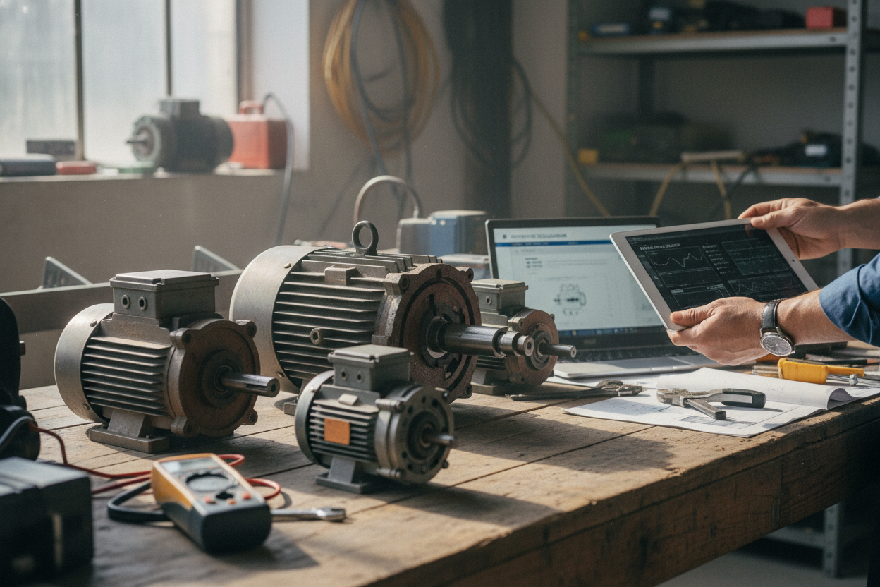
Prototype, Measure, and Iterate. Before committing, build a test setup and validate assumptions. Instrument the system with a tachometer for speed, an ammeter or drive telemetry for current, and temperature sensors on the motor frame or windings to monitor thermal rise. Record starting current, acceleration time, steady-state draw, and any vibration or noise that hints at misalignment or resonance. Compare measured torque (via inferred current) and speed to your model; if peaks are higher than expected, refine the gear ratio, acceleration ramps, and control tuning. Recalculate RMS torque using real profiles, and adjust motor size or cooling if margins are thin. Validate stops and reversals, check brake performance if used, and verify that the duty cycle does not cause cumulative heating. Document results, lock the bill of materials, and plan for maintenance and spares. This disciplined loop yields a motor choice that is efficient, robust, and right-sized for your project.